Consulting for CFD Flow Calculations
The electrical design of standard machines based on magnetically equivalent
circuits, know-how and measured values is fast and easy to perform. After a
rough first dimensioning, the optimization can be carried out with the calculation of different geometry variants and operation points. Developers of
large generators prefer to use their in-house program mostly written in Fortran or programmed with Simulink; these have been tuned with measurement
results. Developers of small and medium standard motors prefer to use commercial tools.
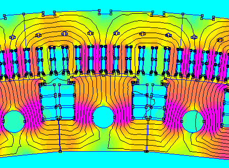
The magnetic field of new electrical machines should be calculated with the Finite-Elements Analysis. It allows to precisely localize the
distribution of the iron loss. For the concept of a long motor, 2D calculations are usually good enough. For large machines, it might be necessary
to perform these calculations for several sections. For more complex and detailed analysis, the calculations should be made in 3D using commercial
software.
The allocation of the electrical losses to the places of production is not a subject of focus during the concept phase; the project members are mostly interested in the values of the total losses and the corresponding efficiency. Good knowledge of the locations of production is however required for temperature calculations.
Losses in electrical machines are divided into ohmic losses (copper losses), magnetic core losses (iron losses), mechanical losses (ventilation losses, bearing losses), and supplementary losses. The copper losses are the dominant losses for most of the machines; they can be determined directly with resistance and current, taking the skin effect into account. The losses in the stator and rotor windings as well as the losses in the stator yoke and in stator teeth caused by the basic field can be homogeneously localized in the associated volumes. With the help of existing FEA magnetic field calculations, the iron losses for larger machines can be assigned even more precisely according to the place of origin.
The iron losses can be calculated analytically using the equations of Steinmetz, Howe or Bertotti. The iron losses are calculated as the specific losses of the steel [W / kg] multiplied by the weight and an empirical coefficient. The specific loss is given in the steel data sheet for 1.5 T and 50 Hz; this value must be corrected to the design flux density and frequency. The empirical coefficient for determining the actual iron loss relates to defects in manufacture, strength and type of lamination, and harmonic waves. It is usually between 1.3 and 2.0.
It is much more difficult to calculate and localize the supplementary losses. Electrical engineers are still struggling a lot with this topic and are usually unable to provide satisfactory input for the thermal calculation. Load-dependent supplementary losses are due to the converter feed-in. Load-independent supplementary losses of the magnetic circuit occur in the air gap. Determining the supplementary losses during the measurement proves to be difficult, especially for fast rotating machines. A typical method for determining supplementary losses is to subtract the measured iron losses from the calculated hysteresis and eddy current losses. Unfortunately, with this method, all measurement and calculation errors are included in the supplementary losses. In addition, items related to hysteresis and eddy current losses that the traditional equations do not cover, such as minor hysteresis loops, also fall into the supplementary losses’ calculation.