HVAC aims to make the thermal sensation more pleasant. We want to avoid drafts, to regulate the humidity and to reduce the effects of
unbearable heat due to solar radiation with regards to energy consumption.
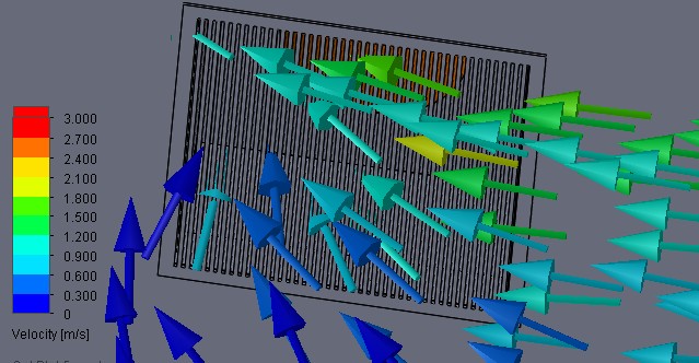
 Streamlines exiting a supply grille
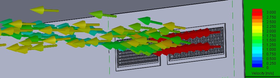
 Streamlines entering an exhaust grille
3D CFD Flow simulation
The ventilation or the decontamination of a room or a building is important enough that it should be drafted at the beginning of the
project. It is required to perform 3D Computational Fluid Dynamics
calculations: this is the only way to estimate the volume flow and pressure
drops and to visualize the flow and the dissemination of the contaminants.
Using these results, the optimization potentials of the initial climatisation
are visible. The optimum climatisation should be ensured and realized with a series of CFD calculations.
Noise reduction
The source of the highest sound pressure level is usually the fan. The sound pressure fluctuations are transported with the air flow via the air ducts and enter the rooms through the supply air grilles.
Turbulence occurs on the supply air grilles, which generates additional noise and thereby causes an increase in the level.
The fan source level is usually determined by the manufacturer using measurements. Normally, information about the average sound pressure level on a so-called 1m distance grid and/or the sound power is common.
If, when recalculating the ventilation system, it turns out that the permissible limit levels in the rooms are exceeded, then in most cases sound obsorbers can be installed in a suitable location.
Choosing a sound absorver is based on measurements, data sheets and experience.
Consulting for CFD flow simulation
We are a consulting company specialised in 3D thermal and flow calculations for ventilation; we use the commercial tools FloEFD and Solid Edge Flow Simulation;
we can also generate a 3D-CAD model. We offer analysis of acoustics to evaluate the noise level in the room.
less contamination
The principle of precaution against infections, microbiological or bacterial contamination, and pollutants requires the installation of a cleanroom.
The proven method is to blow air from the ceiling and to withdraw it from the floor or from the base of the walls. This method should be
implemented if the architecture does not forbid it. The simulation makes it possible to protect the designated clean area from impurities and/or to
evacuate any impurities produced in the room. The final option to be considered is the placing of barriers in the room to protect from contamination.
|
The pressure in the room must set to a precise value, for example, minus 50 Pa. Therefore, some regulator valves must be used; the pressure throttlings
generate additional noise. These valves must be set differently according to the seasons.
A turbulent flow generates larger dissemination than laminar flow. Both flow types can be well calculated with CFD. For the operation room of
a hospital, a laminar block is always installed with flow speeds of 0.3 – 0.5 m/s.
CFD simulations are required to comply with the contamination classes.
|
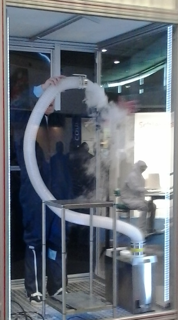
Visualisation of a turbulent flow |
The most common causes for the imprecision of the calculation are leakage of the room or a difference in
the construction and operation of the climatisation
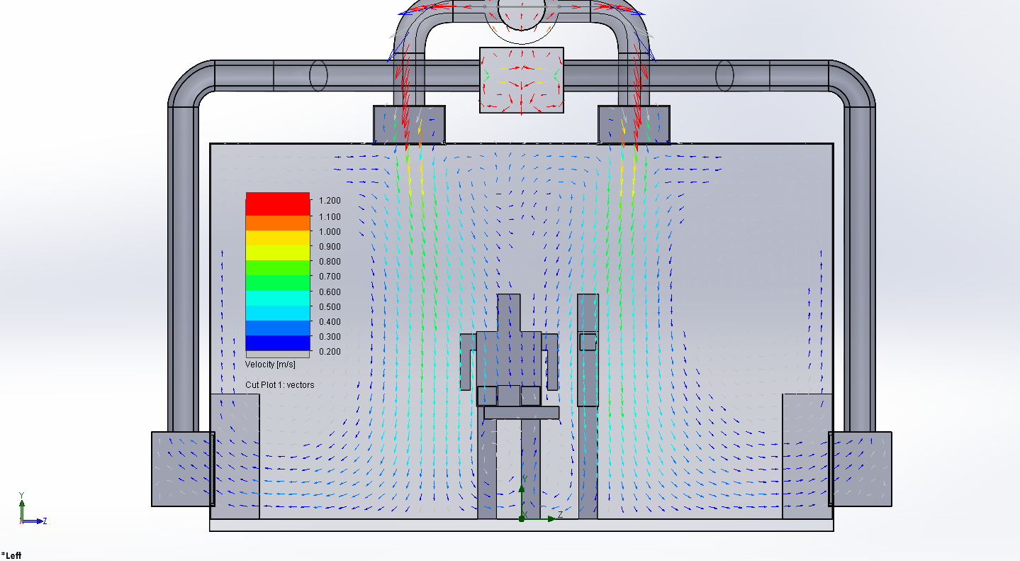
Free convection due to heat loss
Electrical have heat losses. The temperature increase causes changes in the density of the air, which result in a very slow flow speed.
The transport of heat between the solids and the air is called free convection. TWe turned off the clean room ventilation of a microscope with a loss of 1700 kW; The calculated flow around the microscope is 0.4 m/s and flows upwards.
The flow around the microscop should not exceed a speed of 0.1 m/s. Free convection hinders laminar flow. Both flows should be calculated simultaneously using CFD.
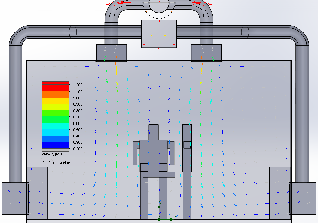
Velocity vectors in an operation room