Heat Sinks for Power Electronics
Thermal Management with Heat Sinks
Modules are usually mounted on a common heat sink, which dissipates the resulting power loss heat.
To achieve a more uniform heat distribution, an additional thermally conductive base plate can be placed between the module and the heat sink.
There are passive and active heat sinks.
Passive heat sinks operate without a fan and release heat to the surroundings through natural convection and thermal radiation.
Active heat sinks, on the other hand, use a fan to deliberately enhance airflow and remove heat more quickly by forced convection.
If the cooling performance is still insufficient, more powerful concepts such as water cooling or heat pipes can be used to transport the heat even more effectively.
All of the cooling methods mentioned can be precisely calculated and analyzed using modern 3D CFD flow simulations, allowing them to be optimally designed already during the development phase.
Thermal Interface Materials (TIM)
When assembling the power module to the heat sink, small air bubbles remain, which greatly increase the thermal resistance.
To mitigate this, thermal interface materials (TIMs)—such as gap pads or thermal pastes—are applied. However, the actual distribution and compression of TIMs often introduce uncertainties, making precise thermal resistance difficult to estimate.
The most reliable approach is to measure this resistance directly and use it as input for further calculations.
Manufacturing of Heat Sinks
Before starting with the design of a heat sink, we must decide how it is going to be manufactured.
The manufacturing method strongly influences the thermal performance, cost, material choice, and achievable geometry of the heat sink.
In most applications, aluminium is the preferred material because it has low thermal resistance, is lightweight, and is easy to process.
Extruded heat sinks are the cheapest solution. Aluminum is easy to push through an extrusion die, allowing long profiles with consistent cross-sections to be produced efficiently.
This method is widely used for standard applications where moderate thermal performance and low cost are required.
Bonded heat sinks are more expensive as fins and base are separate parts. In this approach, fins are manufactured independently and then bonded to the base using thermal adhesives, brazing, or soldering.
This allows higher fin density and more flexible designs compared to extrusion, at the expense of higher manufacturing cost.
3D printing enables highly complex and optimized heat sink geometries that are not possible with traditional methods.
However, it is challenging to use aluminum in many additive manufacturing processes, and the cost of metal printing is high.
As a result, materials with relatively poor thermal conductivity, such as plastics or polymer-based composites, are often used.
This significantly limits the thermal performance of 3D-printed heat sinks, making this technology more suitable for prototyping or low-power applications rather than high-performance thermal management.
Die casting is suitable for high-volume production of heat sinks with complex shapes. Molten metal is injected into a mold, allowing good dimensional accuracy and repeatability.
However, thermal conductivity may be lower than extruded or machined aluminum due to material structure.
CNC milling is used when high precision, custom designs, or small production runs are required.
Heat sinks machined from solid blocks offer excellent thermal performance and design flexibility, but this method is generally the most expensive due to material waste and machining time.
Design of Extruded Heat Sinks
Extruded heat sinks are widely used for thermal management in engineering applications due to their cost-effectiveness and reliable performance. Heat sinks may operate using natural convection, where heat is dissipated passively into the surrounding air, or forced convection, where fans or blowers actively move air across the fins to enhance heat transfer. Each cooling method requires a different design approach to achieve optimal efficiency.
A common design mistake is attempting to maximize performance by increasing the cooling surface area through the addition of more fins.
While this may appear beneficial, it leads to an increased pressure drop. As a result, airflow through the heat sink is reduced and air temperature is increased.
It can ultimately result in increased chip temperatures.
Water Cooling with Cold Plates
Water cooling using liquid cooling plates (cold plates) provides significantly superior thermal performance compared to air cooling. In these systems,
a liquid coolant—typically water or a water-glycol mixture—is circulated through precisely engineered channels within a metal liquid cooling plate to absorb and
transport heat away from electric components.
The internal channel design, often incorporating fins or pin structures, plays a critical role in maximizing heat transfer surface area while minimizing pressure drop.
Computational Fluid Dynamics (CFD) is an essential tool for optimizing liquid cooling plate designs, enabling engineers to achieve an optimal balance between thermal efficiency
and hydraulic performance. This approach ensures that chips operate within safe temperature limits, even under high electrical and power-density loads.
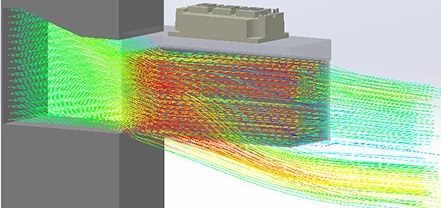
Streamlines through the heat sink of an IGBT power module
Parameter Variation and Design of Experiments (DoE)
The literature on cooling solutions is often outdated and may not reflect current best practices or the specific design requirements. It is more effective to begin CFD design using a proven previous design as a starting point.
The model of the power module with its cooling device is quite small and the calculation time is short. A large number of simulations, usually up to 100, can therefore be performed to optimize the heat sink design.
Parameter variation for a heat sink involves modifying specific geometric variables, such as fin thickness, height, or spacing, to observe their impact on thermal resistance and pressure drop.
Parameter variation for a cold plate involves modifying the number and size of the pins or fins.
This approach helps engineers understand how sensitive the design is to individual changes.
However, varying parameters one by one does not account for interactions between them, which can limit the
potential for finding the truly optimal design.
DoE helps you decrease the number of simulations needed to explore a wide design space.
While the design of standard extruded heat sinks offers limited room for improvement, optimizing more complex heat sinks requires a systematic approach.
A Design of Experiments (DoE) study is an effective method for this, involving a series of automated simulations to explore the design space and identify the most influential parameters.


